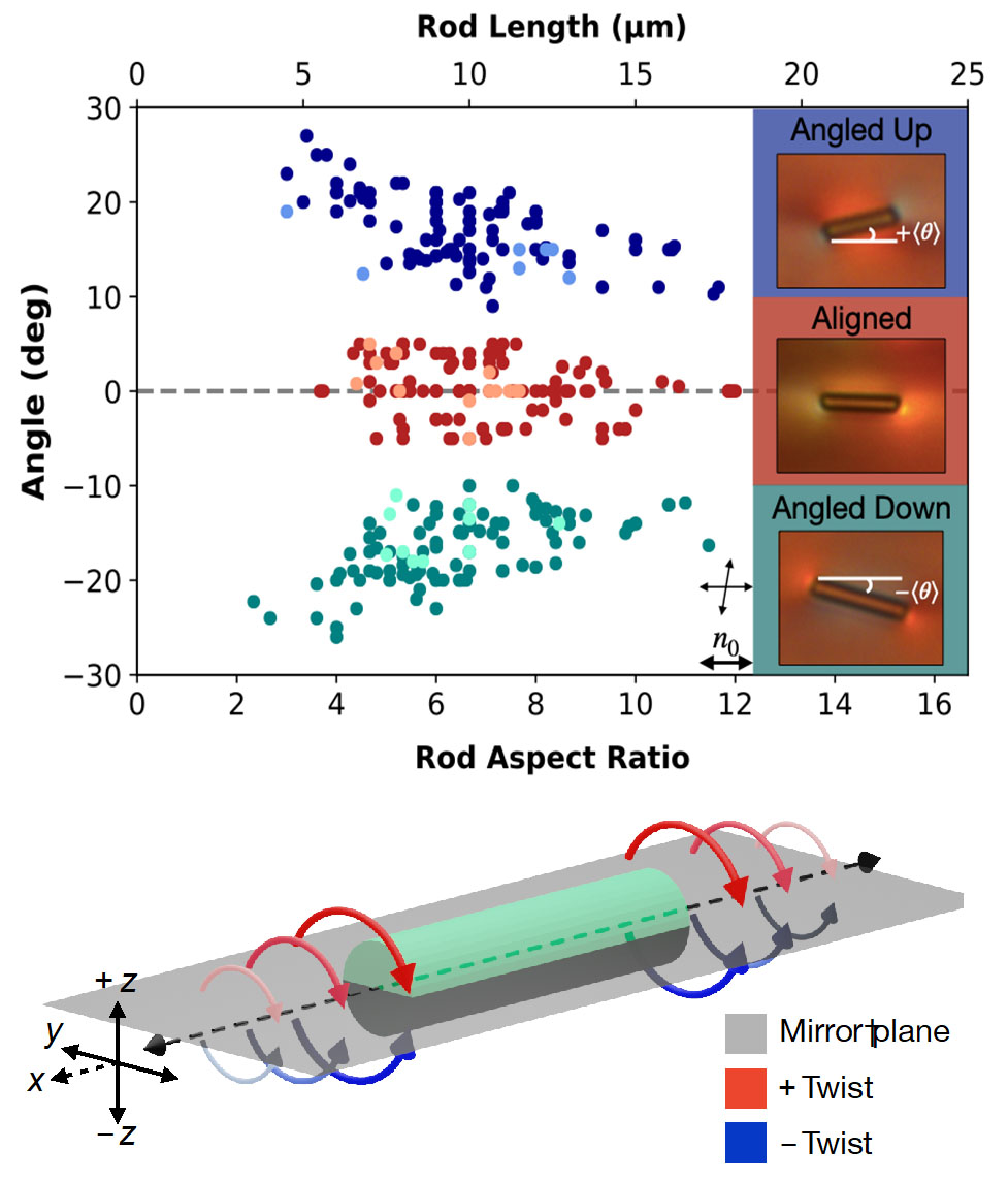
Top Figure: Dependence of rod orientation angle on rod length or aspect ratio. The diameter of all rods is 1.5 µm. The insets show de-crossed analyzer images (top view) of the three types of rods; in these images the colors indicate the handedness of the twist deformation. Black arrows show the polarizer (analyzer) at 0° (80°); the far-field director () is horizontal. Notice that the tails of the aligned (angled) rods twist with opposite (same) handedness.
Bottom Figure: Schematic of the novel director twisting that surrounds the angled rods, i.e., in a longitudinal mirror plane director configuration around an angled rod.